

ReMote: BarCentric Installation Instructions
Wolf Tooth ReMote BarCentric Installation Instructions
Tools Needed
- 2.5 mm hex key
- 2 mm hex key
- 1.5 mm hex key
- Cable cutting shears
- Diagonal cutter or other crimping tool
- We suggest using a new cable (a used cable will work but there might not be enough cable depending on the arrangement)
Installation Guidelines
- Installation will be best performed using a new (uncut) cable. The BarCentric lever is compatible with cables up to 1.2mm in diameter.
- BarCentric is only compatible with mountain-style handlebars (22.2mm diameter)
Mountain Bike Handlebars
The BarCentric dropper lever is designed for situations where handlebar space is limited. The BarCentric is an excellent dropper lever to use when you have a front shifter, a suspension lockout lever, and/or e-bike controls.
These instructions cover installation of the cable at the BarCentric lever. These instructions do not cover routing of the cable/housing through the frame or attachment at the dropper seat post, as these procedures will vary with different frames and different seat posts. For more information regarding cable routing in frame or connection with seat post actuator, please refer to the respective manufacturers of your frame/seat post.
1. Remove left handlebar grip2. Determine optimal location for BarCentric lever. Location and orientation relative to neighboring bar-mounted components and grips will vary depending on individual setup.

3. Route cable through BarCentric assembly using either step 3.a or 3.b below, depending on cable fixing style of the dropper post being used:
- Rotate lever body to position that will allow for desired routing of cable/housing. Secure lever body to handlebar using 2.5mm hex key (Fig 2.a) Torque 0.5 - 1.0 N-m.

- Ensure that the lever paddle can move through its full range of motion without interfering with operation of neighboring components (brake lever, shift lever, e-bike head unit, etc.)
- Determine desired starting location for lever paddle. The starting position is determined by the location of the rotational stop screw. This screw can be placed in one of four potential locations (see Fig 2.c), using 1.5mm hex key.
3. Route cable through BarCentric assembly using either step 3.a or 3.b below, depending on cable fixing style of the dropper post being used:
- Some dropper seat posts have a cable fixing clamp located at the seatpost end of the cable. In these situations, feed cable through lever paddle (Fig 3.a (1))

- The cable-fixing set screw may need to be backed out to allow cable to pass through the lever paddle. Now feed cable through the bend and out the barrel adjuster. The barrel adjuster may need to be temporarily removed to facilitate this step. (Fig 3.a (2)). Once through the bend, feed cable through barrel adjuster and reinstall.

- Most seatposts do not have a cable fixing screw, instead having a cradle for a cable head. In this case, the cable will need to be fed from the seatpost to the lever, with the cable fixed at the dropper lever. After routing cable through its housing, feed cable through barrel adjuster (Fig 3.b). Now feed cable through the lever paddle. The cable-fixing set screw may need to be backed out to allow cable to pass through the lever paddle.


4. Before securing cable-fixing set screw, ensure that the lever paddle is in its starting position (rotated as far forward as possible with the chosen rotational stop screw location). Screw barrel adjuster inward as far as possible. While holding lever paddle at the starting position, pull the cable taut and use a 2mm hex key to tighten the set screw to 1 N-m, securing the cable.

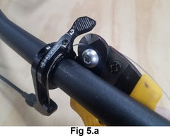
5. Use cable shears to trim excess length of cable extending from the lever. Cut cable 10-20mm from the set screw/fixing point location (Fig 5.a). Install a crimped cable end to prevent remaining cable from fraying (Fig 5.b).

6. All slack in the cable must be removed to allow the lever to function properly. Turn the barrel adjuster counterclockwise to remove any remaining slack and add a small amount of initial tension to the cable (Fig 6). *** Failure to follow this step may result in cable slipping off the lever reel and rubbing on the handlebar ***


